
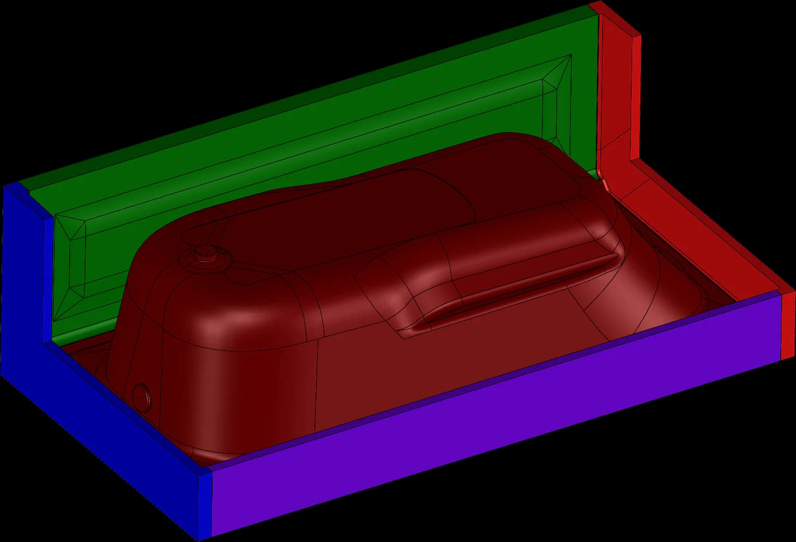
1. Tooling
Start by deciding which face of the part must be controlled by the mold and whether a male or female tool best supports the geometry. Tool material and construction should follow the forming temperature, expected production use, cycle requirements, surface specification, machine setup, and budget—not a one-size-fits-all hierarchy.
Vacuum passages, mounting, sealing, handling, and support belong in the tool plan from the beginning. Plug assists or other forming aids may also affect the pattern and mold design.
2. Draft
Draft is the taper that helps a cooled part release from the tool. Deep walls, textured surfaces, material shrinkage, and the choice between male and female tooling all affect how much is needed. Use as much practical draft as the part allows and avoid treating a single minimum angle as correct for every material or feature.
3. Radius
Generous transitions help heated sheet move through the geometry and reduce severe local thinning. Tight inside and outside corners can be formed in some processes, but they demand closer review of sheet thickness, material, tool side, pressure, and appearance requirements.
4. Draw ratio
Draw ratio is a way to compare the sheet area available before forming with the surface area the material must cover after forming. Deep pockets, tall features, closely spaced walls, and abrupt changes consume material quickly. Evaluate the entire shape rather than relying on one ratio without considering material behavior and the forming method.
5. Undercuts
An undercut can mechanically lock a formed part onto the tool. Some undercuts can be handled through material flexibility, removable tool sections, movable features, or a different mold strategy. Each solution adds practical questions about release, maintenance, repeatability, and cost, so the feature should be reviewed before the tool is built.
6. Ribs and bosses
Ribs can stiffen broad surfaces, and bosses can support attachment or assembly needs. Their height, spacing, radii, and position affect material distribution. Some reinforcement or attachment features are better added as secondary components instead of being forced into the formed geometry.
7. Texture
Texture may come from the sheet, the tool, or a later finishing operation. Mold texture is reproduced most directly on the side of the sheet that contacts the tool. Deeper textures usually make release more demanding and can change the draft requirement, so appearance and demolding must be considered together.
8. Trim, holes, cut-outs, and vents
Thermoformed parts normally need trimming after forming. Establish trim datums from the controlled side of the part and make sure the formed geometry provides a reliable way to locate secondary machining. Some openings can be created by forming a feature and trimming it afterward; others are better cut directly in a secondary operation.
9. Hardware
Fasteners, inserts, brackets, and other hardware can often be added after forming. Some applications may use insert-forming techniques, but the hardware, heat exposure, retention, and release method must be designed around the actual process rather than assumed late.
10. Materials
Thermoplastic sheet is available in many polymers, blends, capped constructions, colors, textures, and grades. Each has its own forming range, shrink behavior, stiffness, impact performance, moisture sensitivity, and surface characteristics. Select the sheet with the material supplier and thermoformer, then make sure the mold is designed for that choice.
When geometry still needs tooling-aware review, start with the information you have.